Boatanchors

  • Boatanchor Frequencies

    BAND FREQ. S M T W TH F S TIME DESCRIPTION
    160 1.8030 X X X X X X 2000 VINTAGE CW
    160 1.8850 X X X X X X X AM HANG-OUT
    160 1.9300 X 1900 VINTAGE / NOSTALGIA
    160 1.9450 1700 VINTAGE AM / GRAY HAIR
    160 1.9850 X X X X X X X AM HANG-OUT
    160 1.9950 0200 EAST MIL. WINTER
    80 3.5100 X X X X X X X BOATANCHOR CW
    80 3.5790 2100 VINTAGE CW
    80 3.5795 X X X X X X X 0200 BOATANCHOR CW
    80 3.5800 X X X X X X X CW BA HANG-OUT
    80 3.7450 X 1200 CANADA BA AM
    80 3.8050 1700 INFORMAL CCA
    80 3.8150 X X AM AFTERNOONS
    80 3.8200 X X AM AFTERNOONS
    80 3.8250 X X AM AFTERNOONS
    80 3.8300 X X AM AFTERNOONS
    80 3.8350 X X AM AFTERNOONS
    80 3.8350 X 0800 VINTAGE CALIF. SSB
    80 3.8370 X 1300 AWA VINTAGE AM
    80 3.8370 AWA VINTAGE SSB
    80 3.8400 X X AM AFTERNOONS
    80 3.8550 X 1400 ARIZONA AM NET
    80 3.8650 X DRAKE SWAP
    80 3.8650 X 1700 DRAKE & ANTIQUE SSB
    80 3.8650 TRADER'S NET
    80 3.8670 1830 AWA AM NET
    80 3.8700 2100 WEST AM SWAP
    80 3.8700 X 0400 Z West Coast AMI Net
    80 3.8700 X 0800 VINTAGE CA. NET AM
    80 3.8700 X X X X X X X AM +/- FREQ EVENINGS
    80 3.8720 X X X X X X X 2130 WEST INFORMAL AM
    80 3.8750 X X X X X X 1500 NORTHWEST AM NET
    80 3.8750 X X X X X X X AM +/- FREQ EVENINGS
    80 3.8750 X 1500 NW AM NET, INFORMAL
    80 3.8750 1700 COLLINS INFORMAL
    80 3.8760 0600 COLO. AM NET, INFORMAL
    80 3.8800 X X X X X X X AM +/- FREQ EVENINGS
    80 3.8800 X 0500 DX-60 ENTRY LEVEL
    80 3.8850 X 1100 S. E. VINTAGE SWAP
    80 3.8850 0230 BEER TOWN TRADERS
    80 3.8850 1630 S. E. VINTAGE SWAP
    80 3.8850 X X X X X X X AM +/- FREQ EVENINGS
    80 3.8850 X 0200 EAST COAST MILITARY
    80 3.8850 X 0600 MID US AM SWAP/TECH
    80 3.8850 1630 EASTERN AM SWAP NET
    80 3.8850 2000 WEST COAST CCA NET
    80 3.8980 SWAP NET
    80 3.9150 X 0930 SWAP NET SSB
    80 3.9450 X X X X X X X 0700 OLD BUZZARD NET N. E.
    80 3.9550 X 1700 COLLINS SWAP EAST
    80 3.9750 X 0930 W. MIL. NO 1ST SUNDAY
    80 3.9750 X 2130 W. MIL. FIRST SUNDAY
    80 3.7250 X X 0900 EST ONTARIO BOATANCHORS
    80 3.7250 X X X X X X X 4 PM/8PM EST
    ONTARIO BOATANCHORS
    40 7.0500 X 1700 1ST WED. VINTAGE CW
    40 7.0500 X X X X X X X 1800 BOATANCHOR CW
    40 7.0500 X X X X X X X 1900 VINTAGE CW
    40 7.0500 X X X X X X X 0100 AWA VINTAGE CW NET
    40 7.0600 X 1500 WEST 40M VINTAGE SSB
    40 7.1600 X 1600 WEST COAST INFORMAL
    40 7.2400 X X 1230 VINTAGE SSB NET
    40 7.2400 X X 1230 WESTCOAST SWAP NET
    40 7.2440 X 0900 AWA VINTAGE SSB
    40 7.2350 X 1400 EST SWAN TECHNICAL NET
    40 7.2500 1300 SWAP NET
    40 7.2800 X X X X X X X 0700 HALLICRAFTERS SSB
    40 7.2840 X 0400 Z Arizona/CA Informal AM
    40 7.2900 X X X X X X X AM DURING DAYTIME
    40 7.2900 X 1100 AM ENTRY LEVEL GEAR
    40 7.2950 X X X X X X X AM FREQUENCY
    40 7.238 X 2000 Z DRAKE TECHNICAL NET
    20 14.0370 X 1700 VINTAGE CW, NO SPEED
    20 14.0580 X X X X X X X FISTS CALLING FREQ.
    20 14.1650 X 1100 WIRELESS SET NO. 19
    20 14.1900 X X 1700 JA1DNQ AM NET
    20 14.2500 X 1400 SWAN NET, MID U.S.
    20 14.2510 X 2300 SWAN TECHNICAL NET
    20 14.2630 X 1200 CCA TECH / SWAP
    20 14.2740 X 1130 AWA SSB VINTAGE NET
    20 14.2750 X 1400 HEATH USERS AM & SSB
    20 14.2860 X X X X X X X AM FREQUENCY
    20 14.2860 X X X X X X X 1500 WESTCOAST AM NET
    20 14.2930 X 1745 HALLICRAFTERS NET
    20 14.2930 X 2030 HEATHKIT NET
    20 14.2930 X 1900 VINTAGE SSB NET
    17 18.150 X X X X X X X AM FREQUENCY
    15 21.4250 X X X X X X X AM HANGOUT FREQ.
    12 24.980 X X X X X X X AM FREQUENCY
    10 29.0000 X X X X X X X 29 - 29.2 AM WINDOW
    10 29.1000 X X X X X X X AM HANGOUT FREQ.


  • Multi-Elmac - AF-67 Trans-Citer

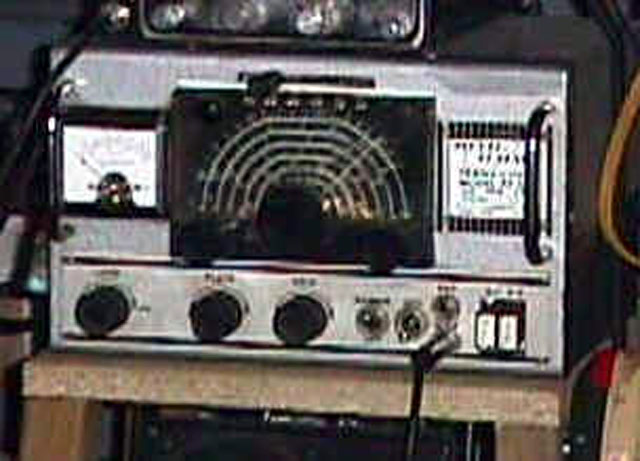
    Multi-Elmac AF-67 Trans-Citer ham radio XMTR

    Description

    1.1 GENERAL. THE MULTI-ELMAC AF-67 Trans-Citer is a ten-tube variable frequency or crystal controlled seven band transmitter or exciter. All circuits are simultaneously switched to the desired band by a single bandswitch lever.Designed as a complete transmitter for mobile or fixed installations, or an exciter to drive a higher power transmitter. When used as an exciter the 500 ohm tap on modulation transformer can be used to drive the higher power modulators.


    1.2 DIMENSIONS. The maximum external dimensions of the AF-67 Trans-citer, excluding projections of control knobs, is 11 1/4 inches wide, 7 inches high, and 8 1/2 inches deep behind panel. Approximate weight is 18 pounds.


    1.3 CIRCUIT DESCRIPTION. The AF-67 Trans-citer employs a variable frequency oscillator with output on wither 1.75 to 2.0 Mc. or 3.5 to 4.0 Mc. In addition to the V.F.O. feature, two crystal positions are included for operation on two spot frequencies. Any crystal that will work straight through, double of quadruple to the desired frequency may be used. The oscillator circuit employs a voltage regulator tube to maintain the plate voltage at a constant level.

    The multiplier stages are broad tuned with a front panel control for peaking the final grid, insuring best performance on all bands. The audio circuit is designed to use either a carbon microphone or a low output microphone such as a crystal or dynamic. A slide switch on the rear apron on the AF-67 Trans-citer sets up the circuit for use with either type of microphone. A reactance tube modulator is incorporated in the variable frequency oscillator circuit for narrow-band-frequency-modulation. The variable frequency oscillator dial scale is directly calibrated in megacycles for each of the amateur bands.


    1.4 TUBE COMPLIMENT. The AF-67 Trans-citer is supplied complete with all tubes, tested in the individual unit, as follows: 

    6AK6 Oscillator
    6BJ6 Reactance Modulator
    6AG5 Buffer-multiplier
    6AQ5 RF Driver
    6146 Final RF Amplifier
    6AU6 Speech amplifier
    12AU7 AF Driver
    5881 (2) PP Modulators
    OB2 Voltage regulator
    #44 (2) Pilot Bulbs


    1.5 OUTPUT. The AF-67 Trans-citer is designed for use with a resonant antenna coupled to its output with a transmission line of 50 to 300 ohms impedance. Other impedance or balanced lines can be coupled through the use of an antenna tuning device. When used as an exciter the coupling link of the high powered final can be directly connected to the AF-67 with a suitable length of coaxial cable. The MULTI-ELMAC AF-67 is designed for a maximum plate power input of 60 (sixty) watts. Maximum ratings for this Trans-citer are 600 volts at 100 milliamperes; or 500 volts at 120 milliamperes. Full 100% modulation occurs when the modulator plate current swings to about 60% of the final plate current with normal voice frequencies.

    1.6 AUDIO. The modulation transformer is provided with a 500 ohm output tap brought to the power plug for driving the grids of high powered modulators. The 5881's will deliver approximately 40 watts of audio with a plate supply of 500 volts.

    1.7 POWER SUPPLY. The AF-67 Trans-citer was intentionally designed to use an external power supply in order to permit (a) use of PMR-6A receiver power supply to supply the low level stages, (b) use of the AF-67 Trans-citer with an AC operated power supply at a fixed or portable location, (c) use of a dynamotor or vibrator supply in mobile installations, or (d) use of the Trans-citer as a driver-exciter for high powered transmitters. A suitable MULTI-ELMAC power supply MODEL PS-2V for portable or fixed station operation from 115 volt AC lines is available.

    1.8 POWER CONNECTOR. A 15 prong female connector is provided with each unit. The 15 prong connector allows all circuits to be arranged for maximum flexibility. Making it possible to use the AF-67 Trans-citer in various types of installations.
    1.9 ACCESSORIES. The following accessories are available for use with the AF-67 Trans-citer:

    PS-2V --- A universal 115 volt AC power supply. (Supplies 6 or 12 volts AC for filaments and two separate high voltages.)
    CFS-1 --- Cable with a 15 prong female connector and fanning strip to connect the AF-67 to the PS-2V power supply.


    Multi-Elmac AF-67 White Paper

    AF-67 Mods & Maintenance by John Conley, W7ZFB


  • Multi-Elmac - PMR-7 Receiver

    Multi-Elmac PMR-7 Amateur Radio Receiver


    Description

    1.1 GENERAL. The MULTI-ELMAC PMR-7 RADIO RECEIVER is a ten tube double conversion superheterodyne covering the 160, 80, 40, 20, 15, and 10 meter amateur bands, plus the standard broadcast band. Designed primarily as an efficient communications receiver for mobile use, it is also especially suitable, because of its small size, for (1) marine and aircraft installations; (2) portable operation; and (3) as a fixed station or monitoring receiver. It is not intended as a converter to accessory to another unit, but a complete receiver, employing a separate power supply and speaker as described in this manual. Every effort has been made to furnish the user with an extremely stable receiver of rugged construction, compact layout, and high sensitivity.

    1.2 DIMENSIONS. The maximum external dimensions of the PMR-7 receiver, including the control knobs are: height 4 5/8", width, 7", and depth, 11 1/2". The depth behind the panel is 9 7/8". The net weight of the receiver is 8 1/2 pounds.

    Accessories

    The ESS-3 "S" Meter is an accessory external 0 - 1 milliampere meter calibrated in "S" units for use with the Multi-Elmac PMR-7 receivers.


  • Multi-Elmac - PS-2V Power Supply

     Multi-Elmac PS-2V power supply

    Specifications

    • 6V. @ 6A. OR 12V. @ 3A. AC for filaments.
    • 230 volts @ 80 ma. DC output.
    • 475 volts @ 170 ma. DC output.
    • Separate filament and plate transformers.
    • Jones barrier strip for convenient connections.
    • Includes a mounted switch which can be used for AC "on-off" or "transmit-receive" switch.
    • Cabinet matches AF-67 Trans-citer.
    • Primary circuit fused.
    • Separate rectifier and filter circuits for each DC output.
    • Both DC supplies use choke input filters
    • Uses 1 - 5U4G and 1 - 6X5GT tube.
    • 24 volt tap on filament transformer for control or bias supply.
    • Size, 11 1/4" wide, 7" high, 8 1/2" deep.
    • Weight, 26 lbs.
    • Designed for use with the Multi-Elmac AF-67 Trans-Citer or a variety of other applications.

  • Multi-Elmac Articles

    IssuePageTitleAuthor
    Oct 1958 QST75Modifications to the Elmac AF67Stewart, Harry - W8PSV
    (now AA4IB)
    Jul 1960 QST60Multi-Elmac M1070 Power-Supply Notes (Hints and Kinks)Stewart, Harry, W8PSV
    (now AA4IB)
    Feb 1991ER 27 Elmac AF-67 Audio Mod

    Seaman

    April 1991ER 28 Elmac AF-67 Modulator Fix

    Winfield

    Jul 1992 ER14The Multi-Elmac CompanySalter
    May 1994ER 20 Multi-Elmac Co., Follow up to in ER #39

    Goldstone

    April 1999ER 12 The Elmac AF-67 Trans-Citer

    This email address is being protected from spambots. You need JavaScript enabled to view it.

    May 1999ER 12 The Elmac AF-68 Trans-Citer

    This email address is being protected from spambots. You need JavaScript enabled to view it.


  • Multi-Elmac Resources


    External Resources 

    Multi-Elmac AM Net

    Wednesday Nights at 7:00 PM CST, 3.880 MHz (except for first Wednesday of month).


  • R.L. Drake - Articles

    Electric Radio Magazine Articles

    Issue

    Page

    Electric Radio Magazine - Article Title

    Author

    Jan-92

    15

    Chenoweth,John,W8CAE, and the R.L. Drake Co.

    Palmer

    Jun-93

    19

    Drake Tube and Antique Radio Net


    Sep-97

    14

    Cooling The Drake TR-4

    Lemay

    Jan-92

    17

    Drake Equipment List

    Palmer

    Nov-97

    33

    Drake RV-6 Remote VFO, The

    Stigall

    Jul-93

    20

    Drake 2B Receiver, The

    Doherty

    Nov-97

    30

    Drake TR-6, The

    Stigall

    Aug-01

    14

    Adding an AM Filter to a Drake TR-4CW

    Covelli

    Oct-01

    34

    Adding AM Filter to a Drake TR-4C

    Gilger

    Oct-02

    40

    New Filters for the Drake TR-4 Transceiver

    Covelli

     http://www.ermag.com/


     Ham Radio Magazine Articles

    Issue

    Page

     Ham Radio Magazine - Article Title

    Author

    Mar-68

    86

    Drake W-4 Directional Wattmeter

    W1DTY

    Aug-72

    6

    Frequency Synthesizer for the Drake R-4

    W6NBI

    Sep-73

    68

    Using Shure 401A mic. with Drake TR-4

    G3XOM

    Oct-73

    58

    Bandpass Tuning Electronic in the Drake R-4C

    Horner

    Sep-74

    74

    Frequency Synthesizer for the Drake R-4 (mod. letter)

    NA

    Jan-77

    79

    Simple tune-up for Drake Gear

    W7DIM

    Nov-78

    88

    Cleaner Audio for R-4C

    K1FO

    Oct-78

    94

    New Product Detector for R-4C

    WB0JGP

    Jan-79

    81

    Improved Tuning on T-4X xmtrs on 160-meters

    W1IBI

    Apr-79

    48

    New Audio Amplifier for R-4C

    K8RRH

    Apr-79

    66

    Split Frequency operation R-4B and TR-4

    WB8JCQ

    May-79

    82

    Backlash Cure for Drake R-4C

    W3CVS

    Oct-79

    78

    Sensitivity Improvement for TR-22C

    K7OR

    Mar-80

    64

    Improving Drake R-4C Product Detector

    W3CVS

    Jan-81

    79

    Drake R-4C Audio Improvements

    W3CVS

    Feb-81

    67

    Woodpecker Noise Blanker of TR-7

    K1KSY

    Feb-82

    28

    Improving Drake R-4C Power Supply

    W3RJ

    Aug-87

    21

    Better Frequency Stability for the Drake TR-7

    HB9ABO


     QST Magazine Articles

    Issue

    QST Magazine - Article Title

    Dec 1965

    TR-4, detailed description (pages 80-83)

    Dec 66

    2-C Receiver

    Dec 69

    L-4B Linear Amplifier; Lange, Walter W1YDS

    Dec 66

    2-NT Transmitter

    Sep 71

    ML-2 Marker Luxury FM Transceiver;  Campbell, Laird W1CUT

    Apr 69

    MN-2000 Matching Network;  Lange, Walter W1YDS

    Oct 67

    MN-4 Matching Network; Grammer, George W1DF

    Jan 74

    R-4C Communications Receiver; Myers, Robert W1FBY

    Jan 80

    R7 Receiver; DeMaw, Doug W1FB

    Mar 92

    R8 Shortwave Receiver; Kearman, Jim KR1S

    Dec 76

    RCS-4 Remote Coax Switch; Cain, Jim K1TN

    Feb 68

    SC-2 2-Meter Converter;Tilton, Edward W1HDQ

    Feb 68

    SC-6 50-Mc Converter; Tilton, Edward W1HDQ

    Dec 70

    SPR-4 Receiver; Blakeslee, Douglas W1KLK

    Oct 97

    SW1 Shortwave Receiver;Lindquist,Rick KX4V

    Oct 94

    SW8 General-Coverage Receiver; Kearman, Jim KR1S

    May 66

    T-4 Transmitter; Grammer, George W1DF

    May 66

    T-4X Transmitter; Grammer, George W1DF

    Feb 74

    T-4XC Transmitter; Sumner, Dave K1ZND

    Jul 70

    TR-6 50-MHz Transceiver; Tilton, Edward W1HDQ

    May 79

    TR-7 HF Transceiver; Sumner, Dave K1ZZ

    Nov 97

    TR270 FM Transceiver; Ford, Steve WB8IMY

    Aug 78

    UV-3 VHF FM System; Kearman, Jim W1XZ

    Aug 68

    W-4 Wattmeter

     http://www.arrl.org/qst


    FAR Circuits PCB Boards

    Communications Quarterly Summer-92

    TR-7 Modifications (4 Board Set)

    HR Aug-87

    Better Frequency Stability For Drake TR7

    QST Jul-82

    WARC and LF on the TR-7

    http://www.farcircuits.net/


  • R.L. Drake Resources

    Everett Hoard, W0HPS (formerly N0NVQ), owner
    PO Box 218
    Lehr, North Dakota 58460

    (877) 372-2341; FAX (701) 378-2551


    • International Radio - Crystal Filters for R-4C and TR-7/R7

    • Drake Service CDs - By Garey Barrell, K4OAH

    • K5DKZ - Convert your T-4 to 6146 with mod kit and more!

    • New Noise Blanker for the R-4C - by This email address is being protected from spambots. You need JavaScript enabled to view it.

    • NU0C - TR-7 Extender Boards

    • Radiophile.com - W1JA's Vintage Drake Station

    • Sherwood Engineering - Modification Kits and Installations for R-4C

    • T & T Drake Repair - Larry Taft,  K2LTand Henry Turner, KC5FLJ

    • WB4HFN - Lots of information on Drake gear

    • 2B Radio Parts - Don Garrett - Replacement Parts for Drake Radio Equipment

    Crystal Suppliers Recommended by Bill Frost

    B D Crystals
    1438 Cox Avenue
    Erlanger, Ky. 41018
    Phone 606-283-5000

    Velco Electric, Inc.
    611 Wangum Road
    Fishers, NY 14453
    Phone: 716-924-2073
    Fax: 716-924-2136


    Other Drake Information 

    Drake User's Net - Tuesday nights, 2000 EST 3865 kHz; technical net on Sunday 2000 EST 7238 kHz 


    Drake Cabinet Paint

    For those who are interested in original Drake paint. That is a true baked powder coat finish, two part system and much more durable than a spray can job. The place to call is Hartzell Mfg. in Miamisburg, OH at 513-859-5955. This email address is being protected from spambots. You need JavaScript enabled to view it. They can repaint your cabinets to like new condx.

    73, Bruce WC1E


    6JB6 Matching Procedure

    I received numerous requests for Bill Frost's description of a procedure to match the 6JB6 finals in 4-line equipment. Rather than send to many individuals, I think the interest is high enough to share the procedure with everyone. It is brief. By the way, I am told by others that Sylvania 6JB6's don't require matching because of their quality.

    73, Wayne, KG5BI


    Dear Wayne,

    Thanks for the e-mail. The 6JB6 tubes were matched on cathode
    current. A fixture was designed and built by the Engineering Dept. that
    kept the operating voltages constant while measuring the cathode
    current. A similiar test can be preformed by using the T-4X or TR-4 as
    the test fixture.

    1. Turn unit off and disconnect power supply. Place the unit upside
    down and remove the bottom cover. Re-connect power supply.

    2. Key the transmitter, with the transmitter gain control at minimum (the
    transmitter should only be drawing idle current).

    3. Measure the voltage at pin 3 of each final tube. The voltage should be
    within .1 or .2 volts to be "matched". Substitute tubes and re-measure
    until all tubes are "matched."

    Regards,

    Bill Frost
    R.L. Drake Service Manager


    Drake E-Mail Reflectors